| |
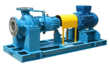
 Hướng dẫn mua, sử dụng máy bơm công nghiệp, bơm cứu hỏa, bơm xăng dầu
 |
|
Hướng dẫn lựa chọn hệ thống định lượng xăng dầu, cần xuất dầu |
|
Tư vấn lựa chọn, sử dụng đồng hồ đo lưu lượng, lưu lượng kế đo nước, đo xăng dầu và đo chất lỏng |
|
Hướng dẫn lựa chọn Barrier tự động, bãi đỗ xe tự động |
|
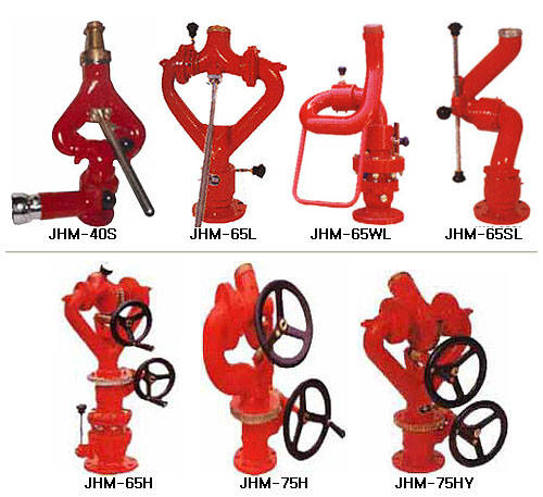
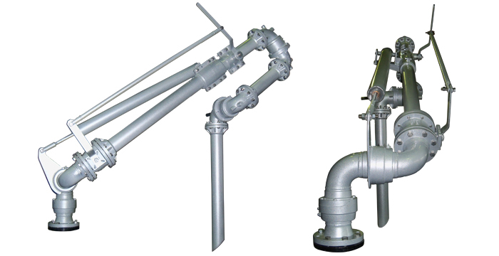
Tư vấn, thiết kế hệ thống chữa cháy, hệ thống báo cháy tựu động, hệ thống sprinkler tự động TCVN |
|
Bí quyết thông thạo các điều kiện Incoterm 2010 trong thương mại quốc tế |
|
| |
| |
 Khách trực tuyến: 27 Khách trực tuyến: 27 |
 Lượt truy cập: 4262 Lượt truy cập: 4262 |
|
| |
|
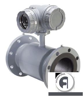
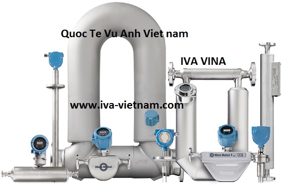
Electromagnetic flowmeter, Ultrasonic flow meter, Mag meter, Vortex flow meter, Turbine meters, Liquids flow sensors
|
|
Electromagnetic flowmeter, Ultrasonic flow meter, Mag meter, Vortex flow meter, Turbine meters, Liquids flow sensors |
| |
| |
| MÔ TẢ |
|
1- Electromagnetic flow meters :
Magnetic flowmeters, also known as electromagnetic flowmeters or induction flowmeters, obtain the flow velocity by measuring the changes of induced voltage of the conductive fluid passing across a controlled magnetic field.
A magnetic flow meter (mag flowmeter) is a volumetric flow meter which does not have any moving parts and is ideal for wastewater applications or any dirty liquid which is conductive or water based. Magnetic flowmeters will generally not work with hydrocarbons, distilled water and many non-aqueous solutions). Magnetic flowmeters are also ideal for applications where low pressure drop and low maintenance are required.
Principle of Operation
The operation of a magnetic flowmeter or mag meter is based upon Faraday's Law, which states that the voltage induced across any conductor as it moves at right angles through a magnetic field is proportional to the velocity of that conductor.
Faraday's Formula:
E is proportional to V x B x D where:
E = The voltage generated in a conductor
V = The velocity of the conductor
B = The magnetic field strength
D = The length of the conductor
To apply this principle to flow measurement with a magnetic flowmeter, it is necessary first to state that the fluid being measured must be electrically conductive for the Faraday principle to apply. As applied to the design of magnetic flowmeters, Faraday's Law indicates that signal voltage (E) is dependent on the average liquid velocity (V) the magnetic field strength (B) and the length of the conductor (D) (which in this instance is the distance between the electrodes).In the case of wafer-style magnetic flowmeters, a magnetic field is established throughout the entire cross-section of the flow tube (Figure 1). If this magnetic field is considered as the measuring element of the magnetic flowmeter, it can be seen that the measuring element is exposed to the hydraulic conditions throughout the entire cross-section of the flowmeter. With insertion-style flowmeters, the magnetic field radiates outward from the inserted probe (Figure 2).
Magmeter Selection
The key questions which need to be answered before selecting a magnetic flowmeter are:
Is the fluid conductive or water based?
Is the fluid or slurry abrasive?
Do you require an integral display or remote display?
Do you require an analog output?
What is the minimum and maximum flow rate for the flow meter?
What is the minimum and maximum process pressure?
What is the minimum and maximum process temperature?
Is the fluid chemically compatible with the flow meter wetted parts?
What is the size of the pipe?
Is the pipe always full?
Insertion Magmeters
Insertion type meters have a standard 1-1/2' or 2" NPT or fit into a specific size fitting. The insertion meters are designed for 2" to 48" in size with a flow rate of 0.05 to 10 m/sec (0.15 to 33 ft/sec). The insertion meters offers an analog output with an integral display for flow rate and totalization. The insertion meters offers corrosion resistant materials, and this type flowmeters are ideal for large pipe applications.
Minimum conductivity: 5 to 20 microSiemens/cm
Installation Considerations: Select a location for the sensor where the flow profile is fully developed and not affected by any disturbances. A minimum of 10 pipe diameters of straight run upstream and 5 diameters downstream is recommended. Some situations may require 20 pipe diameters or more upstream to insure a fully developed turbulent flow profile. The insertion magmeter is sensitive to air bubbles at the electrodes. If there is any question that the pipe is absolutely full, mount the sensor at a 45 to 135 angle.
Grounding requirements: Magnetic flow sensors are sensitive to electrical noise which is present in most piping systems. In plastic piping systems, the fluid carries significant levels of static electricity that must be grounded for best magmeter performance. Instructions are included with the installation manual on how to best ground the magnetic flow meter.
In Line Magmeters
The in line type magnetic flow meters offer a higher accuracy. They can be as accurate as 0.5% of the flow rate. The insertion styles offer a 0.5 to 1% accuracy. The In line meters series in line flange and wafer style meters offer higher flow rates of 1 to 10 m/sec. These in line meters are offered in pipe sizes up to 48".
Minimum conductivity: 5 microSiemens/cm
Installation Considerations: In line flow meters do not require as much straight pipe as the insertion styles. A minimum of 5 to 10 pipe diameters of straight run upstream and 1 to 2 diameters downstream is recommended. In vertical pipe runs, flow should always run up and not down. These flowmeters are very sensitive to air bubbles. The magmeter cannot distinguish entrained air from the process fluid; therefore, air bubbles will cause the magmeter to read high.
Low Flow Magmeters
These low flow mag flow meters are also in line and offer 3/8" to ½" NPT connections. The low flow magmeter series offer flow rates down to 0.38 LPM (.1 GPM). A digital display with relay and analog outputs are standard.
2- Ultrasonic flowmeters :
Ultrasonic flowmeters measure the travelling times (transit time models) or the frequency shifts(Doppler models) of ultrasonic waves in a pre-configured acoustic field that the flow is passing through to determine the flow velocity.
Ultrasonic flowmeters can be categorized into two types based on the installation method: clamped-on and inline.
+ The clamped-on type is located outside of the pipe and there are no wetted parts. It can easily be installed on existing piping systems without worrying about corrosion problems. Clamped-on designs also increase the portability of the flowmeter.
+ The inline type, on the other hand, requires fitting flanges or wafers for installation. However, it usually offers better accuracy and its calibration procedures are more straightforward.
3- Vortex flow meters :
Vortex and other types of “oscillatory” flow meters utilize the behaviour fluid oscillations in order to derive flow rate. This technology works by inducing fluctuations in the fluid properties such as pressure, density or viscosity which can be converted into a flow rate.
When the fluid stream encounters a fixed obstruction, the fluid must divide to pass around the barrier. Because of viscous adhesion, the boundary layer moves slower than the outer layer. At very low flow rates, the viscous forces dominate keeping the fluid attached to the wall of the body and the fluid recombines in a symmetrical fashion. But, as the flow rates increase there comes a point where the flow cannot withstand the adhesion pressure gradient along the surface of the body and boundary layer duly separates from it to form rotating vortices that are carried downstream.
As the flow rates increase even further the vortices become relatively stable and persistent so they line up directly behind the obstruction. The vortex shedding alternates from side to side in sequence and due to the pressure pulse that accompanies the formation of the vortex from the opposite edge. By using this pressure pulse the frequency of this oscillation can be measurement and a flow rate can be derived.
4- Turbine flow meters:
Inline ‘axial’ turbine flowmeters are velocity measuring devices - they measure the average velocity of a fluid flowing through the body of the meter. Mounted within the body of a liquid turbine flowmeter is a vaned rotor. The rotor is centred on a shaft and allowed to rotate on bearings. The shaft is supported in the housing by tube bundles that also provide a measure of flow conditioning for the fluid stream.
The rotor is made from a ferromagnetic material or contains a magnet within the hub of the rotor. Liquid flowing through the meter body engages the rotor forcing it to rotate. The rotational velocity of the rotor is proportional to the average linear velocity of the liquid flow stream. This rotational velocity is transformed into an electrical frequency signal by means of a non-intrusive sensor or coil threaded partially into the body of the meter aligned with the rotational circumference of the rotor. Being in close proximity to the ferromagnetic or magnetic rotor creates an electromagnetic coupling with the coil. The output frequency of the coil then is directly proportional to the rotational velocity of the rotor. This frequency can then be converted to a flow rate indication or scaled signal by dividing the frequency by the meter’s scaling or K-factor (e. g. pulses per gallon or pulses/litre). The K-factor is established by factory calibration of the flowmeter at the time of manufacture.
5- Positive displacement flow meters - Helical screw meter:
Positive displacement flowmeters, also known as PD meters, measure volumes of fluid flowing through by counting repeatedly the filling and discharging of known fixed volumes. A typical positive displacement flowmeter comprises a chamber that obstructs the flow. Inside the chamber, a rotating/reciprocating mechanical unit is placed to create fixed-volume discrete parcels from the passing fluid.
The helical screw principle uses 2 counter rotating gears to form a continuous constant volume cavity. As fluid flows through the meter the screws / gears are forced to rotate. The flowrate is derived from the known volume within the cavity per revolution. In most helical screw manufacturing the gears are machined as a matched pair keeping clearances and very tight tolerances. Relatively little force is required to rotate the screws ensuring the pressure drop is kept to a minimum. As a result they can be selected for very high viscosity fluids and flow rate uncertainties are down to approx 0.1%.
6- Positive displacement flow meters - Round gear (oval gear) flow meters:
Positive displacement flowmeters, also known as PD meters, measure volumes of fluid flowing through by counting repeatedly the filling and discharging of known fixed volumes. A typical positive displacement flowmeter comprises a chamber that obstructs the flow. Inside the chamber, a rotating/reciprocating mechanical unit is placed to create fixed-volume discrete parcels from the passing fluid. In the round gear meter (also called a spur gear meter) the chamber is like two intersecting circles within the body (6). Running in the chamber are two gears (5) sensed by a pickup (1). The fluid travels around the outside turning the gears and creating a positive displacement of fluid for each pulse output.
7- Coriolis flow meters:
Two parallel flow tubes inside the coriolis meter vibrate at their resonant frequency in opposite directions. Any mass flow passing through the tubes delays the vibration at the incoming side and accelerates the vibration at the outgoing side. This causes a small time delay between both ends of the tube. This time delay is measured and is used to calculate the mass flow through the tubes.
By measuring the resonant frequency of the tubes the mass of the medium and - given a constant volume inside the tubes - the density of the medium can be calculated. As both effects are temperature dependent, the temperature is measured via a precise sensor for correcting the temperature effects of flow and density measurement.
As a consequence mass flow, density and temperature of the medium are directly measured. As the mass flow and the specific gravity are known the volume flow can be calculated.
8-Positive displacement flow meter - Rotary piston flow meter (rotary rotor flow meter) :
Positive displacement flowmeters, also known as PD meters, measure volumes of fluid flowing through by counting repeatedly the filling and discharging of known fixed volumes. A typical positive displacement flowmeter comprises a chamber that obstructs the flow. Inside the chamber, a rotating/reciprocating mechanical unit is placed to create fixed-volume discrete parcels from the passing fluid.
In the rotary meters the rotor is basically a disc shape with an annular groove on its underside capable of holding and transporting flow from the chamber inlet to the outlet. Some fluid is also transported in a cavity formed between the rotor outside wall and the chamber wall. A centre 'peg' under the rotor is constrained to run in a circular groove in the body. A web (or plate) in the body is engaged with a slot in the rotor and this modifies the rotation to that of an oscillation as flow passes. It is this oscillation that produces the compartmentation of the fluid into 'positively displaced pockets'. The top of the rotor is equipped with a powerful magnet directly above the 'peg' that is on the underside and so this also has a circular path which allows it to engage and disengage a reed switch sensor located in the top cap above. A volt-free contact closure output signal is given for each oscillation which represents a volume increment. The fluid is transported in a 'positive' manner at all times. The typical metering repeatability is better than 0.2% and a meter accuracy of 1% actual reading is usually obtained over a substantial flow range. For lowest flows the meter will under-read the actual flow in a consistent manner. This allows an improved wide-range system accuracy to be gained by the use of a linearising electronics instrument.
|
|
| |
|
| Hotline:
0989.886.889 |
| Bán hàng Online (Mr Tuân) |
| Bán hàng Online (Ms Xuân) |
| Bán hàng Online (Mr Tú) |
| Bán hàng Online (Ms Thủy) |
| Bán hàng Online (Mr Huy) |
| Chăm sóc khách hàng (After Sales) |
| Admin: tu.hm@vietnam-pump.com |
| |
| |
|